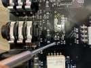
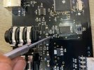
Weird faulty gt22 ?

Soren Kelly

Well-Known Member
Hi can anyone help

I have 2 ext dbl switch
when set up 1/2 for preset up/down it will work fine with both dbl-footswitches with 2 different cables
When i set up 3/4 for the same only 1 switch works on the dblswitch

does that make sens
 
It's possible that one of the switch inputs on the 3/4 jack isn't working - If that's the case, this would require a repair.
 
Hi
Im in Denmark is it possible my local guy can do it or even myself is the Jack sockets mounted/solded directly on the circuit board
 
It's unlikely that it's actually the jack. There is a diode in the circuit that is the first place to look. You can test it using a TRS cable an a voltmeter. Plug the cable into the external switch jack, and leave the other end free. Measure the voltage from tip to sleeve, then measure the voltage from ring to sleeve on the TRS cable. Voltage should measure between 0.9 and 1.1 volts, if it's lower, then the diode is bad. It's a small surface mount component, if you or someone you know is comfortable with surface mount soldering, I can tell you more.
 
Hi well it says
from shield to ring 0,958 V
From tip to shield 0.02v
so it sound like its the diode
im pretty good with a solder and if to hard i have a friend that builds Amps

Cheers Soren
 
Ok, the part you want to replace is D7, located right behind the external switch jack. The part number is SMBJ5.0A-H by Bourns or SMBJ5V0A by On Semi or Taiwan Semiconductor.
 
Hi
This is Really weired
I Dantes to måske sure if it was ext 3 or ext 4 and instead of using the PSU from my axe 3 case i connected a 12 volt 4 amp psu and now all my ext switches works
 
I have now done a lot more research, it turns out that ext switch 3/4 needs to be connected before booting the gt22
if its 1/2 or any of the exp pedals its not a problem but ext switch 3/4 is a different story
maybe a software bug then ???
 
It's unlikely to be a software issue, because I would expect to hear the same report from others if it was. It's very odd that it works when the switch is plugged in at the beginning. Please send me your settings and I can try them here.
 
It's unlikely that it's actually the jack. There is a diode in the circuit that is the first place to look. You can test it using a TRS cable an a voltmeter. Plug the cable into the external switch jack, and leave the other end free. Measure the voltage from tip to sleeve, then measure the voltage from ring to sleeve on the TRS cable. Voltage should measure between 0.9 and 1.1 volts, if it's lower, then the diode is bad. It's a small surface mount component, if you or someone you know is comfortable with surface mount soldering, I can tell you more.

Good evening, Ron. I have the same problem you solved here some time ago. The courier just took my shipment from Bourns, I bought 10 pieces of SMBJ5.0A-H for sure :)
I want to try a fix tomorrow. Do you have any tricks or tips for me to be successful ? Thank you in advance for your willingness
 
Good evening, Ron. I have the same problem you solved here some time ago. The courier just took my shipment from Bourns, I bought 10 pieces of SMBJ5.0A-H for sure :)
I want to try a fix tomorrow. Do you have any tricks or tips for me to be successful ? Thank you in advance for your willingness

It's not too hard to do, especially if you have removed a surface mount part before. This is far from standard practice, and would probably horrify a person who does solder rework professionally, but this is my process: I heat one side of the diode, flow in some more solder, then push up on the diode with the soldering iron so that end comes up off the board. Then, heat and flow some solder on the other side and the diode should come off. The terminals on each side of the diode are flexible, so you can get away with doing this. Then, remove excess solder and put on the new part, paying attention to polarity. This method eliminates the need for specialized equipment like a hot air gun or hot tweezers.

Aside from that, just be sure to follow static electricity precautions, and you should be fine.

We've switched to using the Bourns part a year or two ago, and so far we've had no failures on them.

Excellent. Thanks for the help, tomorrow I will give info about the result.
 
Hello, Ron. Today I replaced the Bourns SMBJ5.0A-H diode at position D7. The resulting work is very ugly, but the voltmeter already shows the correct voltage values of about 1V in both measurements. From the tip to the sleeve, and also from the ring to the sleeve. However, the external button does not work correctly. As a madman, it constantly sends signals to the MMGT 22 without touching it. It first started about a year ago. I left the ext 3/4 button in the user configuration with no function. That was the only way to keep the other buttons working. I didn't deal with it anymore, I just accepted this disorder. When I found this thread about similar problems, I thought it was time to fix it. Unfortunately, I don't know what to do next ...
Once in the user configuration by incorporating ext 3/4, the madness continues
 
Ok, that's unfortunate... Can you please measure the voltage across the newly placed diode (when the GT is powered up) and see if the voltage fluctuates at all?
 
Hello Ron,
Today I worked again to fix the ext input of MMGT 22. I also made the measurements you requested. Here is the procedure and results:

1. I installed new Burns diodes at positions D7 and D8
Measurements before mounting on diodes without power supply: 0.59
Measurements after mounting on non-powered diodes: 0.55
Measurements after mounting on diodes with power supply: 1V

2. I checked the diodes at positions D5 and D6
Measurements on original diodes without power supply: 0.54
Measurements on original diodes with power supply: 0.96V

3. After the measurements, everything seemed fine. The ext 3/4 and ext 1/2 inputs have identical circuits at first glance, I measured the resistors, everything is ok. I also saw the same transistors. I got the idea to exchange transistors Q2 and Q4 with each other. If this replaced the error rate of the inputs, the error would be in the transistors. I did this swap. Everything went well. Only coils 36, 37, 38, 39 I did not solve.

Finally, the last check and done. Then I connected the AX FX III, 4 external pedals and all 4 external buttons. Everything works correctly. I DO NOT UNDERSTAND. Any ideas ???

MMGT_fix_1.jpeg
MMGT_fix_2.jpeg
 
Back
Top