munkywrench
Member
I just wanted to ask here if you would make the schematic available now that interface cables and Amp Gizmos are no longer available for purchase.
Or confirm what I have come up with.
It would be greatly appreciated.
I already deduced what I think it should be.
The EVH uses 16V pulse switching, and not ground.
The required 16V is supplied from the amp on Pin 7 of the 7 pin (not MIDI) DIN footswitch connector.
Pin 3, 2 and 1 (in the 7 pin DIN cable connector) select green, blue, red channels by a momentary short to 16V which is on pin 7.
So the Amp Gizmo should be set so these are momentary, and never on at the same time.
Pin 5 is the FX loop but is pulse-on-pulse-off (again to 16V pin 7), so the state cannot be tracked by the switcher reliably. And I have seen mention that it sometimes doesn't switch if a channel is changed at the same time. I assume it is left out of the interface cable and the FX loop can remain on always. Or perhaps it is connected just so you have some control to get the loop switched on if it is not default-on.
At the Amp Gizmo, the normal function is to short one of the 8 pins to shell - in the manual it says "short to ground" but the shell is actually floating (not grounded) in the amp gizmo.
So I guess the more simple interface cables connect shell to whatever the common voltage is for the amp switching - supplied by the amp footswitch connector - usually amp GND, but for EVH this would be pin7 = +16V.
This means the shell of the connector exposes 16V in the wiring I have come up with (see below).
But the Amp Gizmo casing is also isolated / not case-grounded so there is no risk of a short/current flowing there.
However, I would guess one should careful not to touch the shell to any case grounded parts of any equipment.
The shell of the EVH footswitch cable is connected to GND_LV in the amp, so that should be left unconnected.
The shield of the cable should probably be connected to GND at the amp only. But certainly not to 16V.
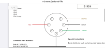
All things considered, what I came up with was: (There is no additional pcb in the 5150 III - AG interface cable)
EVH 5150III ----------------- EVH 5150III 7 pin DIN --------------------- Cable ------------------------- Amp Gizmo 8 pin
(circuit diagram) (cable end connector) (cable end connector)
Pin 1*------------------------ Pin 3 (GREEN pulse select)--------------- conductor -------------------- Pin 1 (Group mode)
Pin 2*------------------------ Pin 2 (BLUE pulse select)----------------- conductor -------------------- Pin 2 (Group mode)
Pin 3*------------------------ Pin 1 (RED pulse select)------------------ conductor -------------------- Pin 3 (Group mode)
Pin 4*------------------------ Pin 5 (FX pulse on/off) --(or leave out)-- conductor -(or leave out)---- Pin 4 (not in Group mode)
Pin 6*------------------------ Pin 7 (16V)-------------------------------- conductor -------------------- Shell of connector
Pin 8*------------------------ Shield (Amp GND_LV) --(or leave out)--- cable shield ------------------/ !!! DEFINITELY DO NOT CONNECT TO SHELL !!!
*Note that the pin numbers of the EVH circuit diagram do not correspond to the 7 DIN cable end connector pin numbering.
I HAVE NOT BUILT OR TESTED THIS YET! As the 8 pin connector is taking a loooong time to arrive.
Or confirm what I have come up with.
It would be greatly appreciated.
I already deduced what I think it should be.
The EVH uses 16V pulse switching, and not ground.
The required 16V is supplied from the amp on Pin 7 of the 7 pin (not MIDI) DIN footswitch connector.
Pin 3, 2 and 1 (in the 7 pin DIN cable connector) select green, blue, red channels by a momentary short to 16V which is on pin 7.
So the Amp Gizmo should be set so these are momentary, and never on at the same time.
Pin 5 is the FX loop but is pulse-on-pulse-off (again to 16V pin 7), so the state cannot be tracked by the switcher reliably. And I have seen mention that it sometimes doesn't switch if a channel is changed at the same time. I assume it is left out of the interface cable and the FX loop can remain on always. Or perhaps it is connected just so you have some control to get the loop switched on if it is not default-on.
At the Amp Gizmo, the normal function is to short one of the 8 pins to shell - in the manual it says "short to ground" but the shell is actually floating (not grounded) in the amp gizmo.
So I guess the more simple interface cables connect shell to whatever the common voltage is for the amp switching - supplied by the amp footswitch connector - usually amp GND, but for EVH this would be pin7 = +16V.
This means the shell of the connector exposes 16V in the wiring I have come up with (see below).
But the Amp Gizmo casing is also isolated / not case-grounded so there is no risk of a short/current flowing there.
However, I would guess one should careful not to touch the shell to any case grounded parts of any equipment.
The shell of the EVH footswitch cable is connected to GND_LV in the amp, so that should be left unconnected.
The shield of the cable should probably be connected to GND at the amp only. But certainly not to 16V.
All things considered, what I came up with was: (There is no additional pcb in the 5150 III - AG interface cable)
EVH 5150III ----------------- EVH 5150III 7 pin DIN --------------------- Cable ------------------------- Amp Gizmo 8 pin
(circuit diagram) (cable end connector) (cable end connector)
Pin 1*------------------------ Pin 3 (GREEN pulse select)--------------- conductor -------------------- Pin 1 (Group mode)
Pin 2*------------------------ Pin 2 (BLUE pulse select)----------------- conductor -------------------- Pin 2 (Group mode)
Pin 3*------------------------ Pin 1 (RED pulse select)------------------ conductor -------------------- Pin 3 (Group mode)
Pin 4*------------------------ Pin 5 (FX pulse on/off) --(or leave out)-- conductor -(or leave out)---- Pin 4 (not in Group mode)
Pin 6*------------------------ Pin 7 (16V)-------------------------------- conductor -------------------- Shell of connector
Pin 8*------------------------ Shield (Amp GND_LV) --(or leave out)--- cable shield ------------------/ !!! DEFINITELY DO NOT CONNECT TO SHELL !!!
*Note that the pin numbers of the EVH circuit diagram do not correspond to the 7 DIN cable end connector pin numbering.
I HAVE NOT BUILT OR TESTED THIS YET! As the 8 pin connector is taking a loooong time to arrive.
Last edited:
")